FreeCAD-manual
An experiment at reorganizing the contents of the FreeCAD wiki in an easier, friendlier book-like manner. The manual is now hosted on the FreeCAD wiki
BIM modeling
BIM stands for Building Information Modeling. The exact definition varies, but we can say simply that BIM is a series of rules that define how buildings and other large structures like bridges, tunnels, etc… are modeled today. BIM models are usually the same kind of 3D models as we have done so far in this manual, but also include a series of additional layers of information, such as materials information, relationships to other objects or models, or special instructions for building or maintenance. This extra information permits all kinds of advanced analyses of the model, such as structural resistance, cost and construction time estimations, or calculations of energy consumption.
The Arch workbench of FreeCAD implements a series of tools and facilities for BIM modeling. Although it has a different purpose, it is made to work in tight integration with the rest of FreeCAD: Anything made with any other workbench of FreeCAD can become an Arch object, or be used as a base for an Arch object.
The BIM workbench is an upgraded, more user-friendly version of the Arch workbench. It also includes several useful tools from other workbenches such as Draft or TechDraw. It is not bundled with FreeCAD by default, but is easily installable through the addons manager. In this exercise, you can use either Arch or BIM, but if you are going to do BIM modeling with FreeCAD regularly, you are highly recommended to install the BIM workbench.
As in the PartDesign workbench, the objects produced by the Arch/BIM workbenches are meant to be built in the real world. Therefore, they need to be solid. The Arch/BIM tools usually take care of that automatically, and also provide utility tools to help you check the validity of objects.
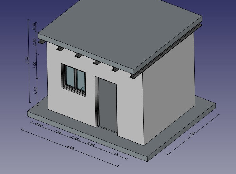
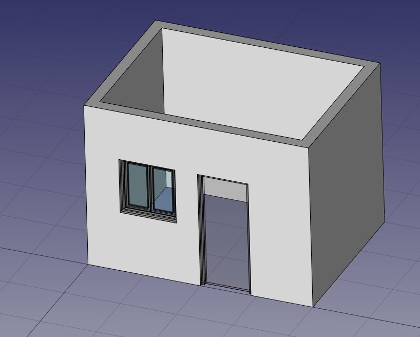
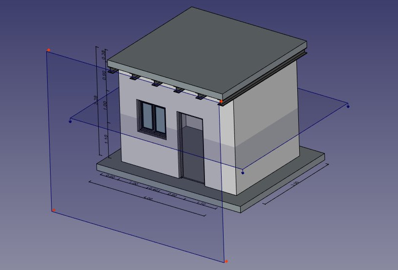
In this chapter, we will see how to model this small building:
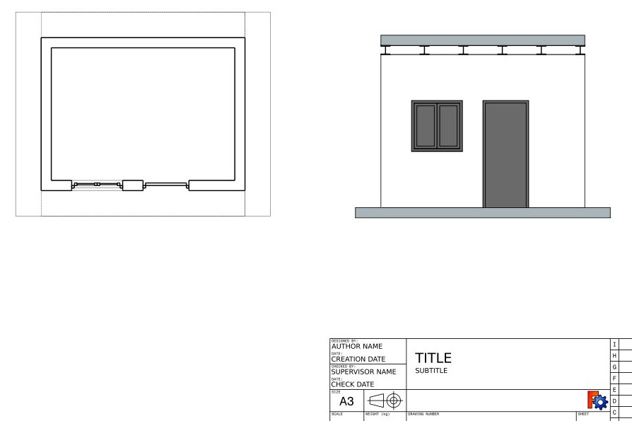
and produce a printable sheet with a plan and a section view from the above model:
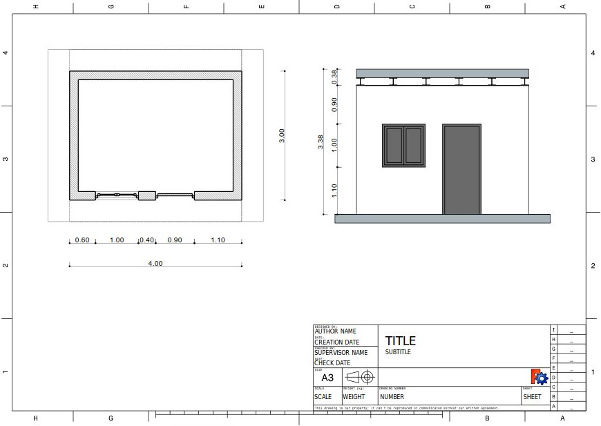
Notice in the sheet title block the cone on it’s side. The graphic is denoting a first angle projection. If the two images were swapped, a third angle projection is declared. In this print it is less important, however in the previous chair drawing it would have had greater significance. First and Third Angle Projection
We are assuming that the exercises in the previous chapters have been preformed, there will be less discussion on previously covered concepts.
- Open FreeCAD, create a new document, and switch to the Arch Workbench.
- Open menu Edit → Preferences → Draft → Grid and Snapping and set the grid spacing setting to 1000mm, so we have a one meter-based grid, which will be convenient for the size of our building.
- On the snapping toolbar, make sure the
 grid snap button is enabled, so we can use the grid as much as possible.
 - Set the Working Plane to XY plane
- Draw four lines with the
 Draft Line tool. You can enter coordinates manually, or simply pick the points on the grid with the mouse (if you enter points in manually, insure the Relative mode is not on):
- From point (0,0) to point (0,3)
- From point (0,3) to point (4,3)
- From point (4,3) to point (4,0)
- From point (4,0) to point (0,0)
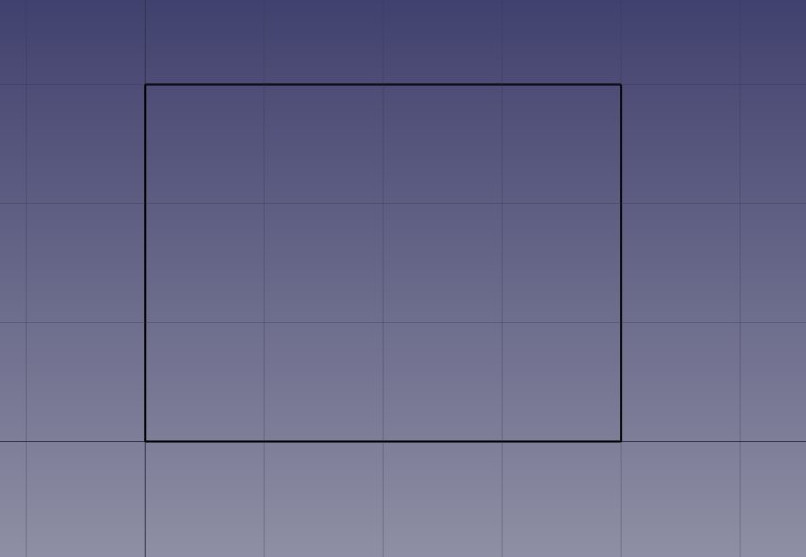
Notice that we drew always in the same direction (clockwise). This is not necessary, but will ensure that the walls that we will build next all have the same left and right directions. You might also think we could simply have drawn a rectangle here, which is true. But the four lines will allow us to illustrate better how to add one object into another.
- Select the first line, then press the
 Arch Wall button. Notice that it will give you a wall with width and height, centered on the original line.
 - Repeat this for the 3 other lines, until you have 4 walls. Currently the walls intersect in the corners and are centered over the original lines.
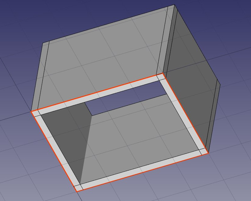
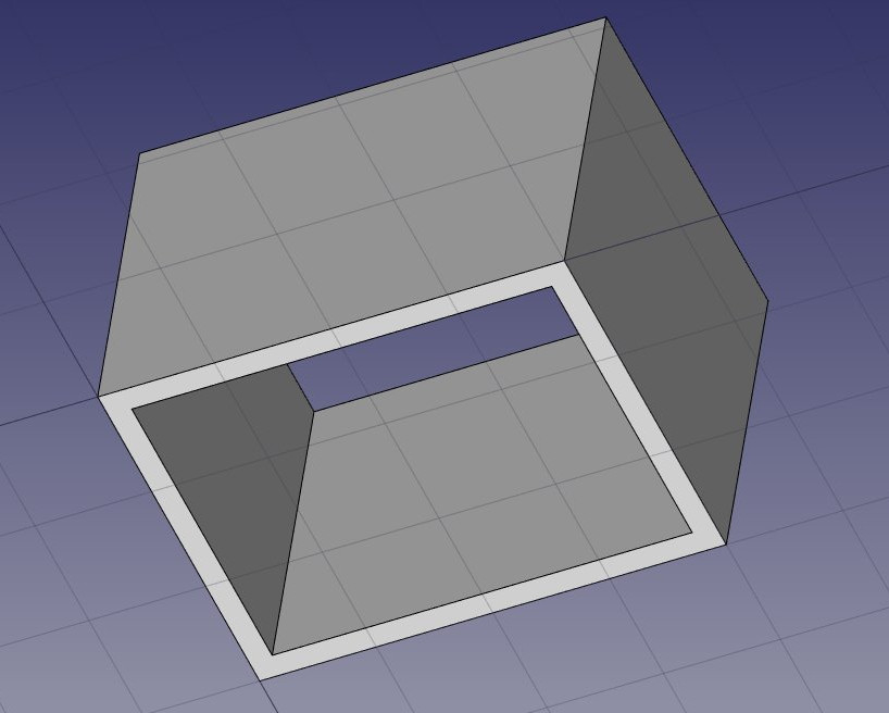
- Select the four walls (highlight all 4 walls in the Model tree), and set their Height property to 3.00m and their Alignment property to left (moving the wall off the center lines.) If you didn’t draw the lines in the same order as we did above, some of the walls might have their left and right directions flipped, and might need to be set to right instead. You will obtain four walls, on the inside of the baselines whose corners fully overlap:
Now we need to join these walls together, so they intersect properly. This is not necessary when your walls are drawn in a way that they already connect cleanly, but here we need to, since they are overlapping. In Arch, this is done by electing one of the walls to be the “host”, and adding the others to it, as “additions”. All arch objects can have any number of additions (objects whose geometry will be added to the host’s geometry), and subtractions (objects whose geometry will be subtracted). The additions and subtractions of an object can be managed anytime by double-clicking the object in the tree.
- Click on an empty space in the geometry window to loose the Model tree highlights
- Select each of the four walls with Ctrl pressed for the second thru end choices, the last one being the wall that you chose to become the host
- Press the
 Arch Add button. The four walls have now been turned into one:
The individual walls are however still accessible, by expanding the wall in the tree view.
- Set the Working Plane to auto so we are not restricted to the ground plane.
- Select the Axonometric View to have a better view of the building front.
- Let’s now place a door. In FreeCAD, doors are considered a special case of windows, so this is done using the Window tool.
- Start by selecting the front wall in the geometry window. This is not necessary, but a good habit. If an object is selected when starting the window tool, you will force the window to be inserted in that object, even if you snap to another object.
- Press the
 Window button.
 - In the window creation panel, in the Preset ** field select the **Simple door value from the pull down list, and set its Width to 0.9m and its Height to 2.1m
- Make sure the
 Near snap location is turned on, so we can snap on faces
 - Place your window roughly on the middle of the front face of the wall:
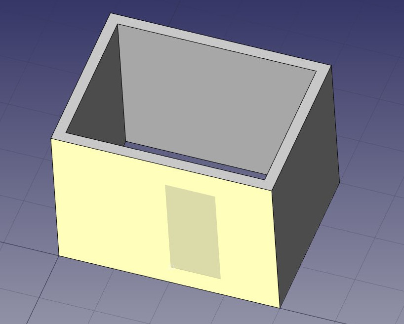
- After clicking, our window is placed on the correct face, but not exactly where we want:
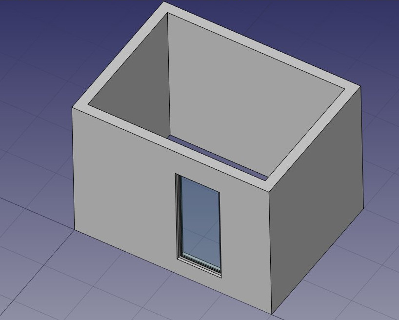
- We can now set the precise location by expanding the wall (in the Model tree click on the small arrow next to the Wall) and the window objects (click on the small arrow next to the Window in the Model tree highlighting the line Sketch) and changing the Placement property of the base sketch of our door (click on the small arrow next to the Placement line in the Data tab, click on the small arrow next to the Position line in the Data tab.) Set its position to x = 2m, y = 0, z = 0. Our door is now exactly where we want it:
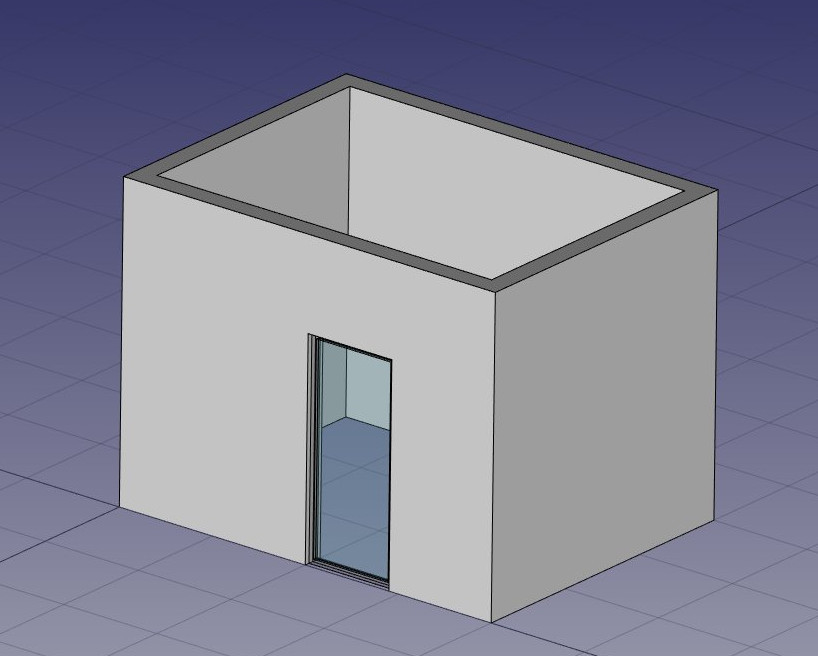
- Repeat the operation to place a window: Select the front wall, press the window tool, select the Open 2-pane preset, and place a 1m x 1m window in the same face as the door. Set the placement of the underlying Sketch001 to position x = 0.6m, y = 0, z = 1.1m, so the upper line of the window is aligned to the top of the door.
Windows are always built on sketches. It is easy to create custom windows by first creating a sketch on a face, then turning it into a window by selecting it, then pressing the window button. Then, the window creation parameters, that is, which wires of the sketch must be extruded and how much, can be defined by double-clicking the window in the tree view.
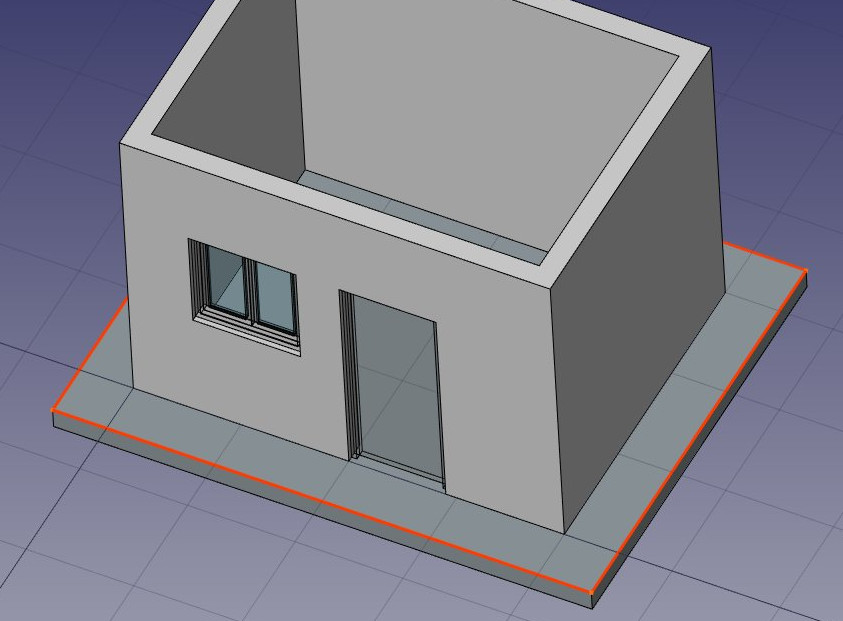
- Let’s now create a slab
- Click on an empty space in the geometry window to clear the highlight in the Model tree
- Set the Working Plane to XY plane
- Create a
 Rectangle with a length of 5m, a height of 4m, and place it at position x:-0.5m, y:-0.5m, z:0. (You may choose to click on Relative to base the second location on the first point, and use the final dimensions 5m x 4m x 0.)
 - Select the rectangle
- Click the
 Structure tool to create a slab from the rectangle
 - In the Data tab set the height property of the slab to 0.2m and its normal direction to (0,0,-1) because we want it to extrude downwards (Click on small triangle next to normal, set z to -1.) We could also simply have moved it 0.2m down, but it is always good practice to keep extruded objects at the same place as their base profile.
- Set the Role property of the slab to slab (using the pull down list.) This is not necessary in FreeCAD, but is important for IFC export, as it will ensure that the object is exported with the correct IFC type. Industry Foundation Class
- Click on an empty space in the geometry window to drop the highlight.
- Let’s now use one of the structural presets to make a metallic beam. Click the Structure button, set the Category pull down to HEB, and in the Preset **pull down select a **HEB 180 preset, and set its height to 4m. Place it anywhere (If you are unfamiliar with the abbreviations, CTH is a circular tube, HEA, HEB, HEM, INP, IPE, are all I-beams, REC is a solid rectangular section, RHS is a retangular tube, and UPE is a channel:)
Sidebar: In the REC category, you will find 2x4in whose metric dimensions are 38mm x 89mm. Converting metric to imperial gives dimensions of 1.496in x 3.504in. This is not in fact 2in x 4in, but it is the actual size of a wooden stud commonly referred to in the construction trade as 2x4. The other items are similarly nominal dimensions of kiln dried construction lumber.
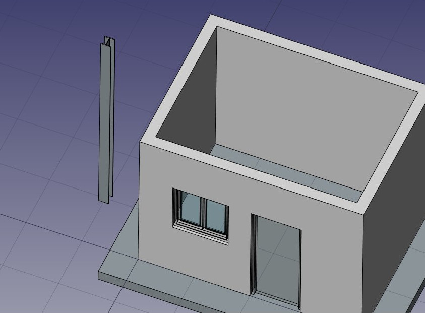
- Back to the I-beam joist, adjust its placement by setting its rotation to 90° in the (1,0,0) axis, and its position to x:90mm, y:3.5m, z:3.09m. (In the Model tree expand Structure, highlight HEB180, in the Data tab expand out Placement, Axis and Position properties, set Angle to 90, and Axis **X=1, Y=Z=0) This will position the beam exactly centered on one of the side walls. If it does not, highlight the **Structure in the Model tree and verify that the Position and Rotation data is set to zero:
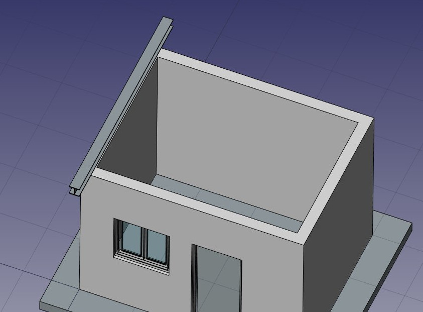
- We need now to duplicate this beam a couple of times. We could do that one by one using the
 clone tool, but there is a better way, to do all the copies at once using an array:
 - Select the beam Structure
- Press the
 Array button
 - In the Data tab, scroll down to the bottom of the list, set the Number X property of the array to 6, leave the Y and Z numbers to 1. Nothing will be visible yet.
- Expand the interval X property, click on the right side of the value field and press the small
 expression icon at the right side of the X field. This will open an expressions editor:
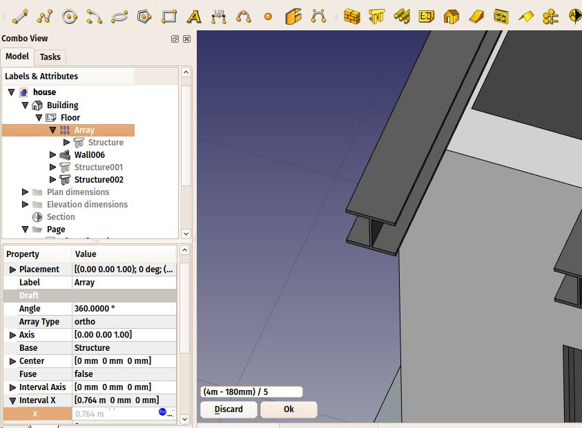
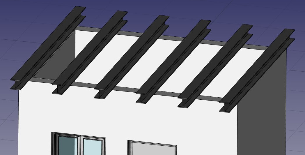
- Write (4m-180mm)/5 in the expression field, and press OK. This will set the x value to 0.764 (4m is the total length of our front wall, 180mm is the width of the beam, which is why it is called HEB180, and we want a fifth of that space as interval between each beam) Click the next line down and the geometry window should update showing all 6 joists:
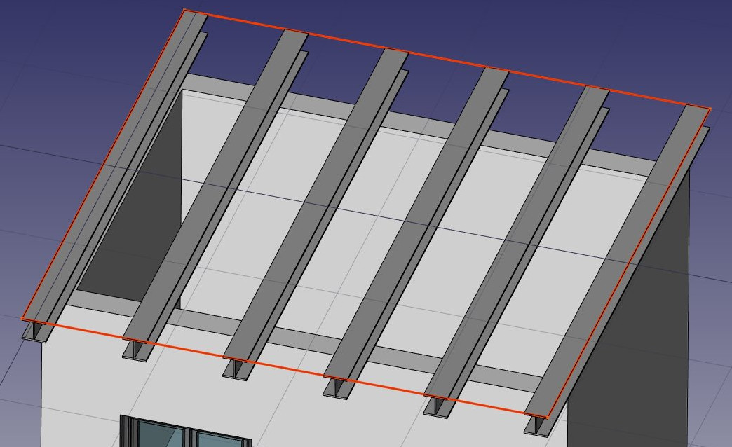
- We can now easily build a simple slab on top of them, by drawing a rectangle directly on the top plane of the beams. Select a top face of one of the beams
- Press the
 Working Plane button. The working plane is now set to that face.
 - Create a Rectangle, snapping to two opposite points of the border beams:
- Select the rectangle in the Model tree
- Click the Structure button and create a slab with a height of 0.2m. If the Slab contains the beams, instead of sitting on top, ensure the Structure is highlighted in the Model tree and in the Data tab, expand the Normal property and set Z=1.0
- Change the Role property in the pull down list to Slab.
That’s it, our model is now complete. Save the file. We should now organize it so it exports correctly to IFC. The IFC format requires that all objects of a building are inside a building object, and optionally, inside a storey. It also requires that all buildings are placed on a site, but the IFC exporter of FreeCAD will add a default site automatically if needed, so we don’t need to add one here.
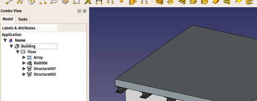
- Select the two slabs, the wall, and the array of beams
- Press the
 Floor button. The selected items will collapse into a single entry Floor.
 - FreeCAD versions earlier than 0.17 will throw errors if the next two steps are executed:
- i. Select the Floor we just created
- ii. Press the
 Building button
Our model is now ready to export:
The IFC format is one of the most precious assets in a free BIM world, because it allows the exchange of data between any application and a construction user, in an open manner (the format is open, free and maintained by an independent consortium). Exporting your BIM models as IFC ensures that anyone can see and analyze them, no matter the application used.
In FreeCAD, IFC import and export is done by interfacing with another piece of software, called IfcOpenShell. To be able to export to IFC from FreeCAD, the IfcOpenShell-python package must be installed on your system. Be sure to select one which uses the same python version as FreeCAD. The python version that FreeCAD uses is displayed when opening the View → Panels → Python console panel in FreeCAD. Or if it is already open scroll back to the start. When **ifcopenshell **is installed, we can now export our model:
- If your FreeCAD version is less than 0.17 skip the export and move on to the dimensioning below.
- Select the object you want to export, that is, the Building object .
- Select menu File → Export . . . select file type: Industry Foundation Classes (*.ifc) and save your file.
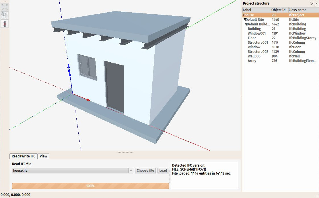
- The resulting IFC file can now be opened in a wide range of applications and viewers (the image below shows the file opened in the free IfcPlusPlus viewer. Checking the exported file in such a viewer application before distributing it to other people is important to check that all the data contained in the file is correct. FreeCAD itself can also be used to re-open the resulting IFC file.
We will now place some dimensions. Unlike the previous chapter, where we drew all the dimensions directly on the Drawing sheet, we will use another method here, and place Draft dimensions directly in the 3D model. These dimensions will then be placed on the Drawing sheet. We will first make two groups for our dimensions, one for the dimensions that will appear in the plan view, and another for those that appear on the elevation.
- Right-click the file name in the tree view, and create a new Group. Right click the new Group and rename to: Plan dimensions and repeat using the new name Elevation dimensions.
- Set the Working Plane to XY plane
- Make sure the
 restrict snap location is turned on, so everything you draw stays on the working plane.
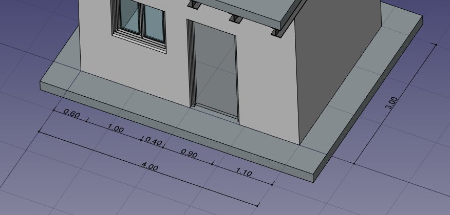
 - Draw a couple of
 dimensions, for example as on the image below. Pressing Shift and Ctrl while snapping the dimension points will give you additional options. If you cannot see the dimension it is likely that the font size is too small. Highlight the dimension(s,) View tab, Font Size Property. A font size of 250mm might be a good starting point.
After adding a few dimensions, it will be come tiring (and time squandering) changing properties for each dimension. Once you have a good idea of the changes needed, you can edit the preferences to create dimensions as desired. Top menu Edit **→ **Preferences → **Draft **→ **Text and dimensions **tab. Make the changes you have decided are needed.
- Select all your dimensions, and drag them to the Plan dimensions group in the tree view
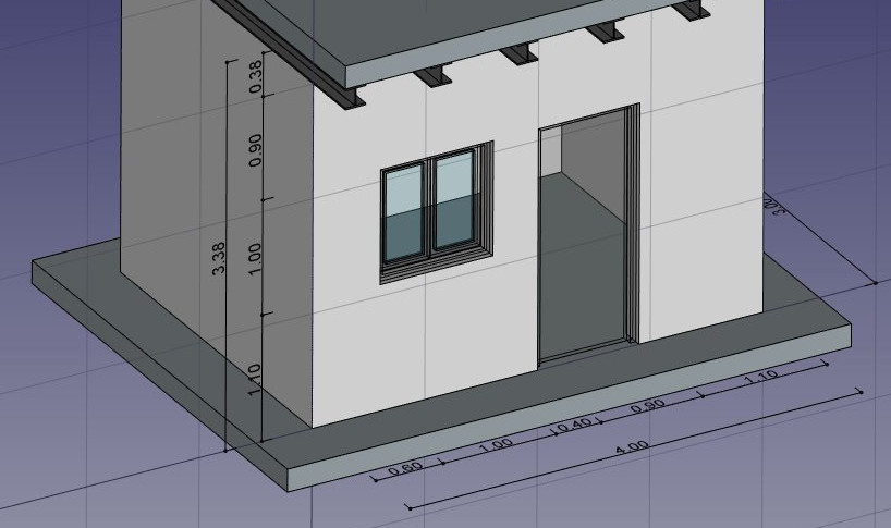
- Set the Working Plane to XZ plane, that is, the front vertical plane.
- Repeat the operation, draw a couple of dimensions, and place them in the Elevation dimensions group.
We will now prepare a set of views from our model, to be paced on a Drawing page. We can do that with the tools from the Drawing Workbench, as we have seen in the previous chapter, but the Arch Workbench also offers an all-in-one advanced tool to produce plan, section and elevation views, called Section Plane. We will now add two of these section planes, to create a plan view and an elevation view.
- Set the working plane to XY
- Select the building object in the tree view.
- Press the
 Section Plane button, and highlight the Section in the Model tree.
 - In the View tab, set its Display Height property to 5m, its Display Length to 6m, so we encompass our house (this is not needed, but will look better, as it will show naturally what it is used for), and in the Data tab, expand out the Placement property and Position property. Set its position at x:2m, y:1.5m, z:1.5m.
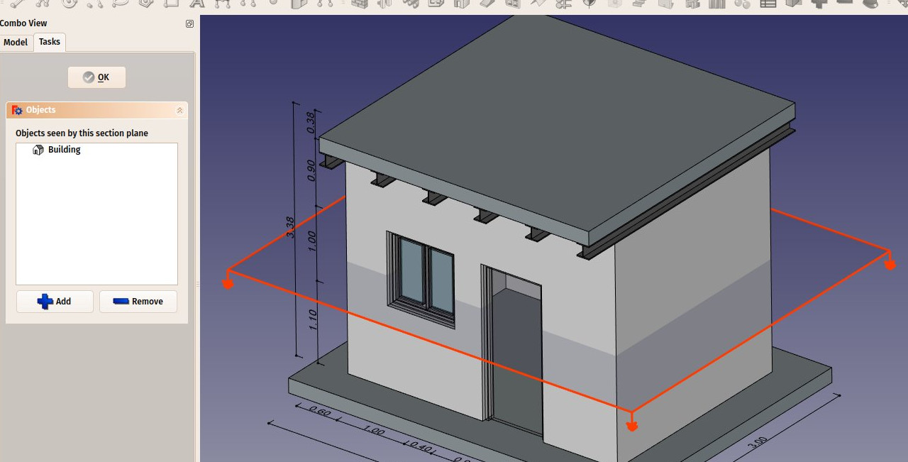
- Check the list of objects included in the Section Plane by double-clicking it in the tree view. Section Planes only render specified objects from the model, not all of them. The objects considered by the Section Plane can be changed here. If the list is empty, click on the wall in the geometry window to highlight it and then click on the **+Add **button
- Click on an empty area of the geometry window to clear any highlights.
- Change the working plane back to Front (XZ)
- Repeat the operation to create another section plane, highlight the new Section plane and give it the same display length and height, and give it the following Placement: position: x:2m, y:-2m, z:1.5m. Verify that this new section plane also includes the building object (by double clicking on the Section in the Model tree.)
- Now we have everything we need, and we can create our Drawing page. Start by switching to the Drawing Workbench, and create a new default
 A3 page (or select another template if you wish).
 - Select the first section plane, used for the plan view
- Press the
 Draft View button. This tool offers a couple of additional features over the standard Drawing View tool, and supports the Section Planes from the Arch Workbench.
 - Expand out Page in the Model tree, highlight View of Section, give the new view the following properties in the Data tab:
- X: 50
- Y: 140
- Scale: 0.03
- Line width: 0.15
- Show Cut True
- Show Fill: True
- Select the other section plane, and create a new Draft View, in the Model tree beneath Page, highlight the new View of Section and in the Data tab, set the the following properties:
- X: 250
- Y: 150
- Scale: 0.03
- Rendering: Solid (If the shed ended up on it side, set the Rotation to 90)
We will now create two more Draft Views, one for each group of dimensions.
- Select the Plan dimensions group
- Press the Draft View button.
- Give the new view the following properties:
- X: 50
- Y: 140
- Scale: 0.03
- Line width: 0.15
- Font size: 10mm
- Repeat the operation for the other group, with the following settings:
- X: 250
- Y: 150
- Scale: 0.03
- Line width: 0.15
- Font size: 10mm
- Direction: 0,-1,0
- Rotation: 90°
You may find that the dimensions are not spaced correctly and the dimensions overlay each other. You can click on the file name tab at the bottom of the geometry window to return to the model. Activate the Arch workbench, click on the dimension you want to move, click on the Move tool, click on the starting position and click on the ending position. Dimension placement will be automatically updated in the drawing sheet.
You may find that something was left out of the Section plane. Click on the file name tab at the bottom of the geometry window to return to the model. Double click on the Section in the Model tree and add the geometry. However you will find that the drawing does not automatically update as before, and we need to force a recompute.
If you do not see the  Refresh icon in the toolbar, there is a Python macro that will force a recompute, or “Redraw” macro Force_Recompute.py
More information about installing macros for the different platforms is here
Complete the title block, click on Page in the Model tree, in the Data tab to the far right of the Editable Texts line there are 3 dots, click on them they form a button. (It may take more than one click.) Edit the text to change the data in the title block. Click on OK when complete.
Save file.
Our page is now ready, and we can export it to SVG or DXF formats, or print it. The SVG format allows to open the file illustration applications such as inkscape, with which you can quickly enhance technical drawings and turn them into much nicer presentation drawings. It offers many more possibilities than the DXF format. Highlight the drawing Page **in the Model tree, in the top menu **File → Export . . . ** Set the **File Type: ** Drawing (*.svg, *.svgz, *.dxf) add a **File Name with a svg extension, and click Save.
Downloads
- The file produced during this exercise: https://github.com/yorikvanhavre/FreeCAD-manual/blob/master/files/house.FCStd
- The IFC file exported from the above file: https://github.com/yorikvanhavre/FreeCAD-manual/blob/master/files/house.ifc
- The SVG file exported from the above file: https://github.com/yorikvanhavre/FreeCAD-manual/blob/master/files/house.svg
Read more
- The Arch Workbench: https://wiki.freecad.org/index.php?title=Arch_Module
- The Draft working plane: https://wiki.freecad.org/index.php?title=Draft_SelectPlane
- The Draft snapping settings: https://wiki.freecad.org/index.php?title=Draft_Snap
- The expressions system: https://wiki.freecad.org/index.php?title=Expressions
- The IFC format: https://en.wikipedia.org/wiki/Industry_Foundation_Classes
- IfcOpenShell: http://ifcopenshell.org/
- IfcPlusPlus: http://ifcplusplus.com/
- Inkscape: http://www.inkscape.org